How to overcome the limits
(they are not god given nor the end of the line......)
To understand how to measure lower THD, you must know how the AP2
analyzer works (in general)
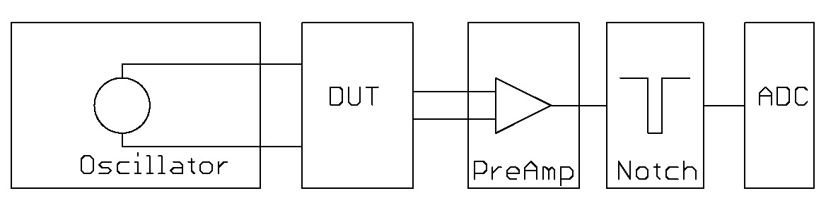
First, you must detect, that the oscillator and or the preamp is the
limiting element,
not the notch (you can see it on the FFTs)
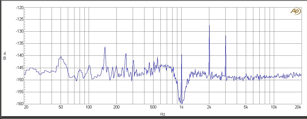
AP2 oscillators FFT after notch (1kHz)
(k2 has -127 dB -> 450nV, k3 has 132 dB -> 250nV, Noise is 150dB
* 141.4 -> 4.5µV --> 5,2µV -> ~ 106dB)
But how to supress k2 (thats even bigger than k3) to test if the
Oscillator or the preamp is the problem ?
Build an active RC lowpass with 1kHz is a solution.
You will loose 3dB of gain @ 1kHz, but that doesn't matter because
THD(+N) is a ratio measurement....
With a 2nd order Lowpass you will win ~12 dB/octave and what's an
ocatve ? Right, the distance from 1kHz to 2kHz is an octave !
So you will supress k2 (2kHz) by approx 10-12dB (all parts are not that
low tolerance :-) and k3 (3kHz) by approx 15-18dB.
That will give more room down to ~ 125-130 dB @ 1V,1kHz
If you would go even further, build a 4th order
lowpass...................
But never (and really never) treat the instruments so far below any
conventional level....
Before treating the THD(+N) display, have a look into the FFT, because
you will see if the Noise floor is the only thing you measure
or your low pass isn't connected (can happen in the middle of the night
:-)
If you have succesfully removed the k2 and k3, you must check in the
FFT, if the signal is supressed enough, else you can estimate THD only
by adding all harmonics....
If there are no harmonics anymore but you can see the signal, you must
add another notch to supress signal further.
(But then, you are at approx. -140dB THD and should think about a new
measurement system or to go out and have some fresh air)
Double check every measurement by changing the frequency well below
your LowPass Filter to see if your circuit is working anymore :-)
Tip #1: If averaging the FFT N-times, you will
lowering the Noise Floor by N
Tip #2: The THD (without +N) will analyze ONLY
the harmonics, not the Noise
Tip #3: The THD+N will measure the voltage after
the notch filter for the fundamental (also Noise, hum,....)
Tip #4: Use a DC sypply wich GND is not
connected to earth.
Tip #5: Move your circuit, all cables and the
measuring instrument (including all external fiilters !) far away from
magnetic and electric fields.
You will be in a region (Noise and THD) were the fluorescent lamp can introduce noise and unwanted
signals, even if it is in the next room !
If you measure 126 dB SNR at 1V level, the
instrument will measure 1µVrms only !
Tip #6: Only use clean boards (old solder flux
can make high impedance connections)
Tip #7: Only use good cables (with defective
or only sometimes defective cables you would only search errors where
are none)
Tip #8: Use shielded and differential cables
wich are as short as possible
Tip #9: Repeat unbelievable measurements many
times until they are repeatable. Check with other frequencies/levels
that your circuit is working anymore.
Tip #10: Be carefull with datasheet diagramms or
results ! They are only valid in a given circuit under given parameters
! (gain, voltage, load, ......)
In some cases, it's difficult to extrapolate it to
other circuits or parameters !
Tip #11: At some point in the development, you must
decide between high SNR, low THD and usability
(an input impedance of 10 Ohms seems not to be
usable for most available opamps wich must drive it)
also lower resistance values decrease noise but will
increase current flow and therefore THD